The newest version of the Raduino software supports RIT (Split) but requires a hardware mod to sense when the PTT is pressed. This is accomplished by adding a 10K resistor to the junction of C150, RV1 and the output of the 5V regulator. Since the 5V regulator is only powered during transmit, the Raduino can sense this voltage to determine if the PTT is pressed. The 10K resistor is connected to the black wire (A0) on the Raduino 8 pin connector.
The 10K resistor and wire can be soldered to the bottom of the BITX40 board to keep it out of the way. I used a small connector in the black wire leading to the Raduino to make it easy to remove the circuit board for further modifications. Some hot melt glue will keep the wire from moving around and breaking off the resistor lead from too much flexing.
73, AL - VE3RRD
The WAX Group consists of members of the Barrie Amateur Radio Club who enjoy building projects for our ham radio hobby from kits or individual parts, instead of just buying ready made. We also promote learning and using CW and getting out of your house to a park or other location to operate (whether it be QRP or higher power, CW or SSB). Webpage: https://barriearc.com/builders-group
Tuesday, May 2, 2017
BITX40v3 Mod - C91 & C92
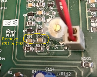
When the BITX40v3 is using the Raduino, the two capacitors C91 and C92 should be removed from the circuit board. These capacitors attenuate the signal coming from the Raduino which is not as big a problem on LSB (injected RF around 5 MHz or less), but is more of a problem on USB (injected RF around 19 MHz). In the newer Raduino sketches (such as v1.0.9 or higher) the drive level for LSB and USB can be set in the software.
The above picture shows an older BITX40v3 board where L4 had to be removed; on the newer boards, both L4 and the variable cap above it are not installed.
The wires from the Raduino to the connector shown above, should be kept as short as possible and routed in an arc up away from the circuit board. Even better is to replace the two wires with mini coax such as RG174. This will minimize the Raduino signal that could enter the circuit and cause other problems such as the harmonic mixing that causes a "birdie" on 7199 KHz.
I can still hear the birdie on 7199 on my BITX40, but it is quite low and doesn't interfere with signals on or near that frequency. 73, AL - VE3RRD
Subscribe to:
Comments (Atom)


